
Dynamic Absorbers – Myth and Reality
Abstract
Dynamic absorbers provide an interesting solution for resonance problems for a variety of applications.These devices have been previously described in publications for applications for fixed speed operation service where an added dynamic absorber splits the natural frequency at the operating speed into two peaks and the vibration is greatly reduced at operating speed.
This sort of application has historically been considered to be useful only based on the following assumptions:
- System operates at a fixed speed (like 1xRPM vibration for constant speed machine)
- The dynamic absorber is essentially an undamped spring-mass system that is added to the original system with about 10% or more modal mass
- The dynamic absorber is NOT useful if the exciting frequency varies or if it has broad band excitation
These restrictions are not valid for the general application of a dynamic absorber as described below based on the belief that achieving 90+% vibration reduction is acceptable for most applications. In fact, the application for broad band (or variable speed) services is shown to have significant value and can functionally eliminate resonance concerns on a system for broad excitation frequency range provided that a properly designed and applied absorber is employed.
Description
Dynamic absorbers have been an interesting solution to resonance issues. The concept is simple:
- You have a natural frequency that is being excited (resonance) with excessive vibration
- You build a spring-mass system using 5-15% of the “modal mass” of the system and tune to the same frequency as the natural frequency
- Attach to the original system and observe the vibration drop to almost zero
- Vibration on the “absorber” ends up quite high with amplitude set by the dynamic force in the machine and the mass of the absorber (F = mass x acceleration)
Challenges to Success
The success story of the dynamic absorber depends on a couple of significant facts. The most obvious is that the absorber needs to be tuned to the right frequency. The second challenge is that the tuned frequency needs to stay constant and not shift/move over time (along with the original system natural frequency). The third challenge is that the now very extreme vibration on the absorber must be tolerable for the design of the absorber spring so it does not fail in fatigue. A final consideration is a general safety concern that WHEN the absorber spring fails in fatigue and the absorber mass falls down that it will not damage the equipment or harm personnel as it falls.
I recall a design I installed on a centrifugal pump that was a basic mass on the end of an all-thread rod that could easily be screwed into the lifting eye threaded hole on top of the pump bearing housing. I built this to prove the concept that a dynamic absorber could work to reduce vibration on the pump for the fixed speed service. I also assumed that if it did work, that we would proceed with a proper design that would have something other than a threaded rod for the spring. It worked fantastic, and after some fiddling with it I achieved about 90% reduction in vibration that got the overall vibration down to the 0.1 in/sec pk range. The customer was happy and I left the site with the joy of solving a vibration problem with a solution using scrap I found in the maintenance shop dumpster that required some simple machining to get it mounted.
spoke to the client several years later and asked if they had ever proceeded with a proper design (since they did not want to pay me for an “engineered” one). The response was that they did not need to, since they started to stock all thread of the right length and knew to replace it about once per week, and to adjust the mass up/down until it “…vibrated like crazy…” and the pump vibration was again near 0.1 in/sec pk. The description was that “…the absorber got full and the rod needed replacing…” since they found over time that it would fatigue after about the same operating time.
A final challenge/concern is that even though the target natural frequency is split into two frequencies (described later) so that the resonance is moved away from the original frequency, two relatively undamped natural frequencies now exist instead of 1 that can now be excited to similar levels if the exciting frequency ever shifts.
Tuning
Dynamic absorbers have been an interesting solution to resonance issues. The concept is simple:
- You have a natural frequency that is being excited (resonance) with excessive vibration
- You build a spring-mass system using 5-15% of the “modal mass” of the system and tune to the same frequency as the natural frequency
- Attach to the original system and observe the vibration drop to almost zero
- Vibration on the “absorber” ends up quite high with amplitude set by the dynamic force in the machine and the mass of the absorber (F = mass x acceleration)
Anyone that has built a dynamic absorber has probably had the experience of discovering that the ideal design that you came up with doesn’t work. This is a common problem with the typical “mushroom style” dynamic absorber that I wrote about years ago.
It would be easy to design a simple dynamic absorber using a cylindrical mass (I’ve used blind flanges a number of times) along with a threaded rod (all-thread of adequate length) as the spring and then weigh the disk to get the mass and calculate the cantilever stiffness of the rod as:
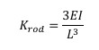
This is the standard stiffness equation for a cantilever beam. There are a few challenges with this (and the use of all-thread) in that you need to know the effective stiffness diameter of the rod (probably close to the diameter for tensile area) and make sure you are using the length to the center of mass for the disk.
Using this approach, if I use a disk that is 6” OD and 1” thick along with a ¾” diameter rod that has a length of 11.9” from the base to the center of mass on the disk, I should get a 30 Hz tuned frequency based on a Mass of 8.8 lb (mass of disk + 50% of mass of the rod) and a stiffness of 806 lb/in. This is using E=29.0×10⁶ psi and density of 0.2836 lb/in3.
Experience will confirm that minor variations from the assumptions (actual effective stiffness diameter of the rod, material properties, etc.) as well as the possible flexibility of the attachment point of the absorber to the original system will end up with the absorber not tuned ideally if setup as described above. This is why the device must be “tuned” after installation unless the design is adequate to control the effective K and moving mass per the design intent.
Absorbers of this type that I have made have always required the mass to be moved down on the rod (make the rod shorter and stiffer) to get the device tuned. I have always assumed that the reasons were some mixture of the following:
- The cantilever stiffness was an estimate and not 100% accurate
- Material assumptions may be off a bit (density, modulus, etc.)
- The connection point provided some flexibility so that the actual rod stiffness is lower because it is not “rigid” at the tie point
- The disk has inertia as well as mass that I have not considered in the design
There may be additional causes, but I suspect these are the primary contributors.
Since the absorber built like described above (very undamped) will have high amplitude vibration, it is likely that the jam bolts on the disk or the jam bolt on the base may come loose or the rod may begin to crack in the treads at the base. If anything gets loose, the stiffness will drop and tuning is off. If the rod begins to crack at a thread root, the stiffness of the rod will decrease quickly (before it breaks off).
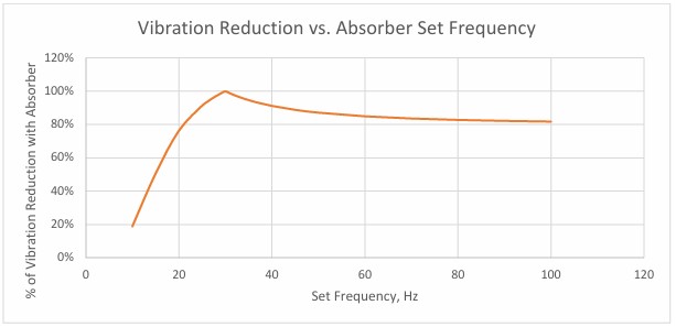
Figure 1 - Performance vs. Set Frequency
To help review the actual performance and benefit of an absorber of this type, a system as follows was reviewed:
- System modal mass of 100 lb
- System natural frequency of 30 Hz
- System damping of 1% (this is about typical)
- Absorber mass of 10 lb (10% of the modal mass)
- Absorber damping level on absorber of 0.4% (a little more than material damping)
- Absorber design set frequency of 30 Hz
The impact of the actual tuning of the absorber vs. performance is shown in figure 1. This suggests that it is better to set the absorber frequency higher than needed so that if (as) the frequency drops, it still maintains some usefulness. Note that the above graph was generated based on a main system with 1% modal damping (typical level) and an absorber damping level of 0.4% (a little more than material damping).
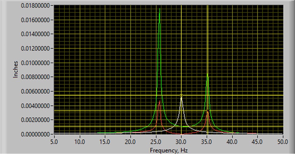
The unfortunate fact with this sort of absorber design is that although the response at the operating speed of 30 Hz is dramatically reduced, there is still a 1% damped natural frequency looming right below and another right above the current operating frequency of 30 Hz. For the perfectly tuned setup and 10% modal mass, the original 30 Hz natural frequency is split into 2 frequencies, with the lower one at 25.7 Hz and the upper one at 35.2 Hz. Any excitation near those frequencies will produce vibration with moderate amplitude.
For the perfectly tuned system, the response vs frequency is detailed in figure 2 that shows the response without the absorber (white line), the system response with the absorber (red line), and the response of the absorber (green line). The red line shows that any excitation above or below the original 30 Hz target frequency can produce higher response on the original system at now two frequencies and that the dynamic absorber vibration at those frequencies will be extremely high.

Figure 2 - Frequency Response with and without Absorber
Damping
One of the key myths for the design/selection of dynamic absorbers is that they need to be undamped to work. This myth is based on the calculated response using undamped system features. When this is done, you will identify that the vibration on the original system goes exactly to zero if there is no damping. For reasonable practical systems (~1% damping on the original system and ~0.4% damping on the absorber), that is not the case, but it can result in very low system vibration when properly applied.
If you care to experiment with the math, it is theoretically possible to drive ANY system vibration to zero by adding an undamped dynamic absorber to an undamped system whether it is a resonant system or not. However, once some reasonable damping is added to the system model, the dynamic absorber will have little or no benefit unless the original system was resonant.
If the system as described is modified to have higher damping levels in the absorber, the performance drops off as damping increases at the original frequency as shown in figure 3. Although the vibration reduction is lower with damping present in the absorber, a vibration reduction of 90% would commonly be quite a victory!!

Figure 3 - Vibration Reduction vs Damping
Applications
The next myth on dynamic absorbers is that they cannot function in a useful way for variable speed machines or broad band vibration sources (turbulence, cavitation, etc.). This myth results from reviewing the undamped equations that define the system response where you quickly observe that if the input frequency varies (or there is broad band energy at all frequencies) that the perfectly undamped absorber doesn’t work very well because the vibration at the 2 new frequencies is no better than the vibration at the original frequency.
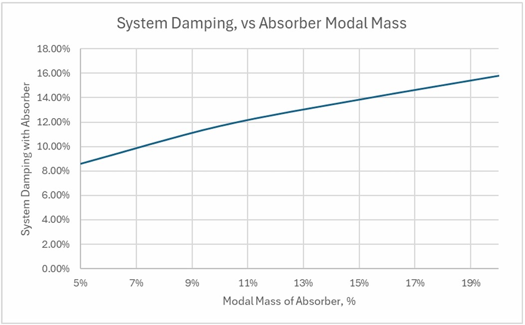
Additional review will show that the better method for reviewing performance on the damped absorber is to evaluate the total system damping level that is achieved by adding a damped absorber. It can be determined that there is a relationship between the modal mass of the absorber and the optimal level of damping for the absorber hardware to produce an optimized design and the best compromise for the system.
The damping described below is the minimum damping level achieved on both of the two natural frequencies that result in the system after the absorber is added provided that the absorber is optimally tuned. Optimal tuning includes selecting the best damping level for the internal absorber mass as well as the set frequency for the absorber. Optimal tuning of the damped absorber requires setting the absorber frequency lower than the target system frequency due to the damped system response characteristics.

Figure 4 - System Damping vs Absorber Mass
Since the original system will often have a starting damping level in the range of 1%, the addition of a damped dynamic absorber with 10% modal mass can reduce the amplification factor from 50 (for the 1% damped original system) to only 4.28, or a reduction of over 91%. That means that the maximum vibration observed due to broad band energy or as excited by a variable speed machine will be 91% lower with the damped absorber compared to the original system.
From a general design perspective, if the damping level for the system is 15% of critical damping (as can be achieved with 20% modal mass), the original natural frequency is considered unresponsive and no longer a concern.
Summary
There are two myths that are not accurate regarding dynamic absorbers:
- Dynamic absorbers need to be undamped to work correctly
- They are only useful for fixed frequency excitation systems (fixed frequency vibration source at the resonant frequency)
Both of these myths are dispelled based on the fact that 90% vibration reduction can be easily achieved using a damped dynamic absorber of appropriate sizing and design. In addition, it is shown that the use of the damped dynamic absorber can help control vibration for either broad band sources or for a wide range of input frequencies as would occur for a variable speed operation.
Applications that are ideal for damped dynamic absorbers would include small bore piping such as vents and drains, longer unsupported piping such as at turns in pipe racks, vertical motors that operate on variable speed drives, and a variety of other systems.