Transmitted Vibration
For the transmitted vibration case, the dynamic system for the piping will be as detailed in figure 1 which is the standard method of describing a mechanical system that is excited by motion from something else (i.e. transmitted vibration).

So for the transmitted vibration case, X ≈ Y x Ǫ at resonance or X ≈ F . So if the damping of thepiping network is 1%, X = 50 Y. At 0.1% damping, X = 500 Y.
This estimation method will work very well for small piping systems that are connected to a mechanical system at one location such as for a standard vent or drain that is cantilevered from a parent pipe. However, for more complex networks including a routed pipe from point A to point B, the excitation input will be closer to something in between the vibration at point A and the vibration at point B.
Forced Vibration
This condition will occur due to dynamic forces acting on the piping usually away from pipe supports with the dynamic forces caused by either pressure pulsations in the piping or by fluid momentum due to slugs of liquid and gas or general flow turbulence. In some cases, fluid forces can be self-generated due to flow induced vibration, but that concept is beyond the scope of this paper.
Pressure pulsations will be generated by any machinery that produces pulsing flow such as reciprocating pumps or compressors or any positive displacement compressor or pump. These pulsations are caused by the periodic variation in the flow rate from the machine, with the amplitude of pulsation dependent on acoustical resonances in the piping network and the exciting frequencies from the equipment. The acoustical resonances are a function of the fluid and the length of the piping and not related to the mechanical natural frequencies on the piping system. When acoustical resonances occur, the pulsation levels in the piping are significantly amplified resulting in very high forced response.
In some cases, the source of pulsations will not be due to periodic pulsation such as for the reciprocating machine, but rather due to general flow turbulence from the flow in the pipe. As the flow rate increases, the general flow turbulence increases with the square of the velocity in the pipe. So if the flow doubles, the vibration due to turbulence will increase by a factor of 4. Flow turbulence is different as well in that the frequency content will be rather large with more of a “broad band” spectrum response. This type of flow induced source will excite a number of natural frequencies in the piping network.
Two phase flow is becoming more common with some oil and gas processing as well as in petrochemical plants where 2 phase flow (some liquid and some gas) can occur particularly downstream of control valves if the fluid is flashing (vaporizing) at the control valve. Two phase flow will produce large forces caused by the fluid momentum (normally the liquid “slug”) reacting at elbows, tees or closed ends from the direction change of the fluid. At an elbow, the fluid hitting the elbow from one direction will have a reaction force to stop and turn the fluid into the other direction. The reaction force is approximately at a 45◌֯ angle from both inlet and outlet on the elbow.

The standard single degree of freedom approach to defining the forced response is detailed in figure 2. As shown above, the vibration is proportional to force and amplification factor and inversely proportional to stiffness.
Specific impacts of changes to the mechanical system for forced response at a single frequency:
- Double stiffness = ½ the vibration
- Double the force = twice the vibration
- Reduce amplification factor by 2 = ½ the vibration
- Adding mass will not directly change vibration at the natural frequency, but will change the amplification factor due to shift in natural frequency
Specific impacts of system changes to the mechanical system for forced response for broad band or variable speed input forces:
- Double the stiffness:
- Will shift the natural frequency up to 141% of original
- Will reduce the general response by a factor of 2
- Vibration at the new resonance will be about ½ of the current value
- Double the force – twice the vibration
- Double the damping of the system:
- Reduce the amplification factor by 2 at resonance
- Reduce the vibration “near” the natural frequency
- Double the mass:
- Will reduce the natural frequency down to 7% of the original
- May reduce amplitude at resonance by up to 30% due to more effective damping due to the lower natural frequency
Assessment Challenges
There are a variety of challenges for assessing piping vibration with one of the important considerations being the piping fabrication details. Threaded piping is much more prone to failure than butt welded pipe. Welded fitting details can also contribute fatigue risk since forged fittings such as Weld-O-Lets have dramatically lower stress concentrations than even socket weld fittings.
As an example, the method of assembly for socket welded fittings (one of the most common piping fabrication methods) can have a huge impact on actual peak stress. A socket weld fitting should be installed with a gap between the end of the pipe and the fitting when it is welded together tominimize the residual stress at the weld due to thermal shrinkage of the weld during fabrication. If that is not done correctly, much higher stresses can occur. Unfortunately, you can’t inspect for that without X-ray imaging which is not often done for general review of piping.

Another consideration for the socket weld fitting is the shape (slope) of the weld between the fitting and the pipe. Using a longer weld (down the pipe) with 2:1 slope is preferred over a 1:1 fillet weld, with even more preference for smooth profile. These minor details can have a large impact on the peak stress at the corner of the weld. And that is the location where fatigue cracks are the most common.
The variety of different layouts will impact the risk tremendously. The list below details some common concerns:
- Threaded fittings should always be avoided on piping if possible
- Particularly at small bore branches connected to larger piping
- If threaded fittings are required, consider using a Thread-O-Let forged fitting
- Butt welded fittings are always preferred over socket weld
- Forged fittings (Weld-O-Let or similar) is always preferred for the first connection to larger pipe for all small-bore pipe (don’t ever weld small pipe directly to larger pipe)
- Use small-bore branch connection self-reinforcement (see ASME guidelines) when possible
- Stainless steel can be preferred over carbon steel pipe in some cases
Table 2 – Stress Intensification Factors
| Connection Description | SIF (stress concentration) | Comment |
|---|---|---|
| Butt Welded Pipe | 1.0 | Best bet… |
| Forged Fitting | Weld-O-Let, Sock-O-Let at connection to main pipe |
|
| Socket weld (low SIF) | 1.15? | 2:1 weld ground smooth |
| Socket weld | 1.3 | Normal 1:1 weld |
| Threaded pipe | 2.3 | Bad idea for fatigue risk |
| Pipe on pipe | >2.1 | Depends on weld details |
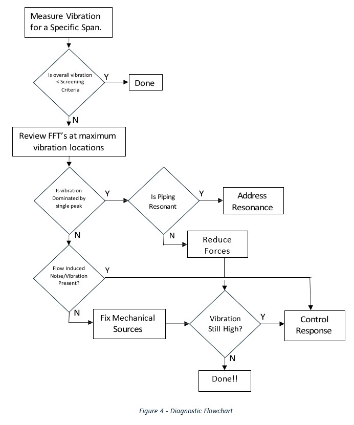
Pipe Vibration Diagnostic Flowchart
The following flowchart can be used to guide piping assessment. This approach is similar to using an ASME OM-3 scan technique that is common on the nuclear power industry with additional diagnostic considerations through the process.
Measuring Vibration on Piping
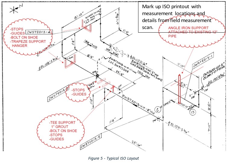
The best approach is to print out a piping isometric drawing or sketch one up yourself with graphical routing of the piping along with notes where valves, supports, branches, etc. are located. The scan should normally be done between pipe supports or at least on a run from a fixed location to the next fixed location. An example ISO is shown in figure 5. Mark up a copy of the ISO with point names/numbers. I normally write the maximum overall vibration at each point for the initial review since that makes it easy to identify where to review the FFT’s for actual frequencies.
I normally set up for the scan using a data collector with a triaxial accelerometer and a route set up to measure all three directions at once. The route is setup up with a number of points starting from one end of the pipe to the other with spacing of about 2’ down the pipe. Mark the points on the isometric drawing for later reference.
After the scan is complete, compare a pre-selected scanning threshold to overall vibration velocity to determine if additional investigation is necessary. During the screening test, the piping should be in service with “normal” operation. If there are abnormal operating conditions to consider, the scan must be repeated for all operating conditions. If the vibration is believed to be driven by variable frequency forces (such as vane pass frequency from a variable speed pump), it may be necessary to continuously monitor the piping at representative locations through the whole operating speed range.
Once overall vibration readings are known, compare the values to your pre-set screening threshold. If all values are below the screening threshold, the line can be declared not at risk. Any observations from operational personnel or other sources that suggest vibration is elevated compared to the values observed during the screening process should trigger another screening event.
If the screening criteria is exceeded, review the FFT plots for points with the highest vibration for additional diagnostic guidance.
Review of Vibration FFT’s
The FFT plots for the points with highest vibration should be reviewed for frequency content. The results from this review will trigger which additional analysis steps should be taken.
The first assessment is to identify if the vibration observed is from a single peak (single frequency) or more of a broad band vibration with lots of energy everywhere.
If the vibration is very dominant at one frequency, that means that either there is a very large force on the piping (or very high transmitted vibration) at a single frequency or that there is a natural frequency on the pipe near that frequency. If this occurs, the next step will be to test to determine if there is a natural frequency near the excited frequency.
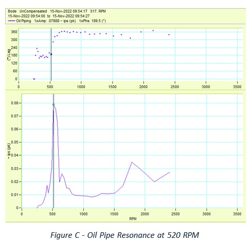
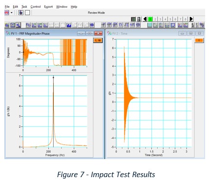
The natural frequency test is normally a bump test but can also be a speed sweep test for a variable speed machine. This can be done by varying speed on a variable speed system and looking for the peak response speed as detailed in figure 4, or by doing an impact test (bump test) when the system is not operating as detailed in figure 5.
Once you know what the natural frequency is, you can then assess the amplification factor to determine how much influence that the natural frequency is having. The impact of amplification factor and damping level is detailed in figure 6.
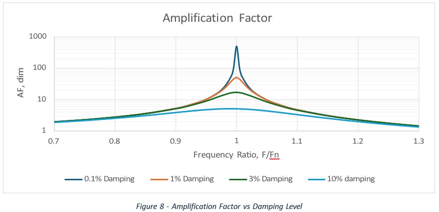
For practical levels of damping on most piping systems (up to 3% damping) there is little impact on amplification factor as long as the frequency is at least 10% away from resonance (0.9 to 1.1 F/Fn). If your natural frequency is within 5% of the exciting frequency, then the system will be in resonance and addressing the natural frequency is a good place to start.
If the damping level can be increased to 10% or so, there would be some noticeable improvement near the natural frequency up to at least +/-10% of the natural frequency.
It should be noted that with 10% separation there is still an amplification factor of about 5 for common damping levels. So the vibration will be 5 times higher than if the natural frequency did not exist.
If the vibration response is rather broad band, then the likely cause is going to be more of a broad band flow induced noise such as from either flow turbulence (high velocity in piping), pump cavitation or recirculation, or other broad band source.
Controlling Response
Once you have exhausted all the options to reduce forces with no success, you are down to needing to control the response with dynamic changes to the piping system.
The options for changing the response include:
- Stiffen the piping (i.e. add supports)
- Add mass
- Add damping
- Add a dynamic absorber
Stiffening the Pipe
Before going into actual stiffening benefits, it should be noted that the piping system should be inspected before going any further to assure that all the expected supports as detailed on piping isometric drawings do actually exist and are functioning. After that is confirmed, you can consider stiffening the piping.
One of the best long-term solutions can be adding additional piping supports. That is not always the case, but it is generally a positive step. When should pipe stiffening be considered very cautiously:
- Piping that operates at either relatively high or low temperatures
- Thermal movement of piping may require significant flexibility
- For large thermal movements, adding supports can result in piping failure due to excessive static stress
- In some cases there may be indeterminant loading on the pipe due to additional supports
- If this occurs, extreme loading at one or more supports could cause the pipe to be overstressed
- Strong consideration should be given to required pipe flexibility and vibration control
Short term efforts can be done to evaluate to benefit of adding some support by using temporary stiffeners. Some of the methods used may include adding pipe stands, wood blocks, chains, etc. Any effort to add a temporary stiffener should consider the actual stiffness of the device used and the stiffness of what it is connected to. Chains and web straps tend to be rather flexible and don’t work well as stiffeners in general.
Any effort to stiffen piping should not be done without proper review of static (and dynamic) stresses in the piping network by using an approved engineering review method for piping stress. It must also be considered that shifting the frequency up by 20% (to get off a resonance with adequate separation margin) will require the system to be 144% stiffer!! That implies a LOT of stiffening.
Any effective stiffening that is added will accomplish two things:
- The added stiffness will reduce vibration since X = F/K x amplification factor
- Any increase in K will reduce F/K
- It will shift the natural frequency higher
- This could be better or worse depending on where the natural frequency starts out
- If the natural frequency is below the exciting frequency, adding some stiffening can push the natural frequency right into resonance.
- Any modifications should on paper target 20% separation from known excitation frequencies
The amplification factor before and after modifications should be reviewed to estimate if the solution will make vibration better or worse after changes.
For a very basic stiffening review, adding an additional support at the midspan of a simply supported section may increase the natural frequency by a factor of 2.8. So adding additional stiffeners can be a very good method to eliminate pipe resonances.
Serious consideration should be given to the stiffness of the actual stiffener. Figure 9 shows one attempt at adding temporary stiffeners to determine if that would be an effective method to address resonance (i.e. high vibration). The stiffness of the stiffener and the stiffness of the end connections can in some cases make the stiffener so flexible that it has minimal impact on the natural frequency. When a temporary wood block is “hammered in” it is also possible (and likely) to deform the pipe (or machinery) due to the required forces to get the member installed (and effective) that the machinery misalignment or additional static stress can be imposed on the equipment or piping. For piping that has already vibrated a lot, hammering in wood stiffeners can result in pipe failures due to the large added static stresses. So proceed with caution!!!!

Dynamic Absorbers
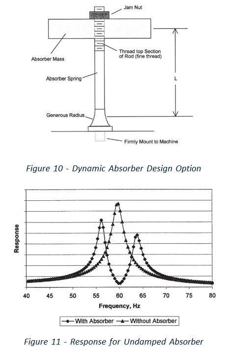
I published a paper years ago about dynamic absorbers with the general response and benefits with details on how to build one. At the time my general conclusion was that dynamic absorbers could be a useful approach for solving resonance problems for fixed speed machines. For that application, the ideal approach is to have an undamped of an absorber design as possible and tune it to drive the original vibration to nearly zero.
This design approach was detailed in the Vibrations magazine Volume 19 No 4 2003. The general design was as detailed in figure 10. This is an undamped dynamic absorber design that can works well to reduce vibration at a specific speed (based on tuning of the absorber natural frequency) but ends up converting the original natural frequency into two natural frequencies on either side of the original frequency as shown in figure 11.
As an alternative, a damped dynamic absorber can reduce the amplification factor over a broad frequency range for any natural frequency within reasonable proximity to the tuned target frequency as detailed in figure 12. The ideal arrangement for a damped dynamic absorber will include the following:
- Use about 15% of the modal mass of the main system as the moving mass for the damper
- Add optimal damping (depends on actual details of parent system and target frequency)
- Tune the device for a specific target frequency
When applied in this way, it is possible to get up to about 13.5% modal damping for the original mode. Using additional damped absorbers can further reduce vibration over a broad frequency range as well.
