
Summary
A 1.5-inch branch line with a thermowell and threaded component was modeled to determine the best location for a ZetaQuest Rohr 1.5 vibration damper. The natural frequency was calculated to be 93.16 Hz with field report of similar natural frequency, with the branch line and thermowell moving together, confirming that the Rohr 1.5 is a suitable damping solution.
The preferred installation location was identified to be on the thermowell flange instead of on the end of the threaded hardware. Installing a Rohr 1.5 – 84.2 Hz at the end reduced vibration to 0.89 in/s and thread stress to 614.88 psi. Installing a Rohr 1.5 – 120 Hz on the flange further reduced thread stress to 357.81 psi, with a vibration of 1.01 in/s. The flange location provides the greatest stress reduction, while the end location provides slightly better vibration reduction.
Actual vibration on the thermowell with the damper located on the end was identical to the calculated vibration with the damper mounted as described. Slightly higher vibration and slightly higher stress at the WeldOLet and slightly higher vibration with the damper mounted at the flange were selected as a preferred option since the stress at the threaded connection was improved. Either option with the Rohr damper installed was found to be a dramatic improvement in vibration and operating stress over the original configuration.
Background
Thermowells are common in the petrochemical and refining industries for temperature measurement in piping systems. The thermowell is attached to the main pipe using a side branch so the thermowell is inserted into the branch connection so that the end of the device is near the center of the pipe. A typical thermowell is shown in figure 1.
In figure 1, the various types of thermowells are shown where the main difference is whether it is attached to a flange on the pipe or using a threaded coupling or other threaded fitting. The length of the device (U) will be determined based on the size of the pipe and the length of the side branch connection so that the end is near the center of the pipe when installed.
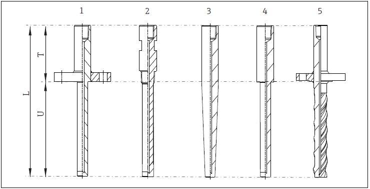
The temperature sensing device is inserted into the end of the device using a variety of threaded fittings with the actual sensor (either a thermocouple or RTD) located near the end of the device near the center of the pipe. The thermocouple is intended to provide a pressure barrier so that the process fluid cannot leak out or get to the temperature sensor.
The inserted thermowell will have a variety of shapes with options being cylindrical, tapered, stepped, or with helical strakes. The shape and diameter of the inserted device can generate unsteady flow downstream of the thermowell that has a dynamic response that can make the thermowell shake side to side in the flow path. There can also be dynamic forces in the direction of fluid flow, but the normal consideration is for vibration in the direction perpendicular to the flow in the pipe.
Vortex Shedding
The vibration source on the thermowell is vortex shedding. This occurs when the flow passing over the device will dance to the left and right with a repeating pattern as shown in figure 2. At very low flows, the flow passes over the cylinder then converges after it passes the cylinder with little dynamic response. As the flow rate in the pipe increases, the flow characteristic will change to be like option c) in figure 2 where there are eddies that move from one side the other in a harmonic pattern.
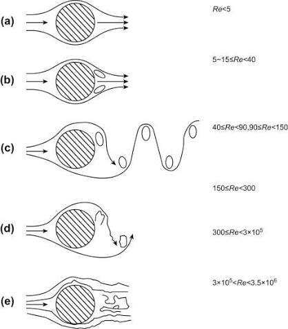
The frequency that the flow “dances” is set by the flow velocity in the pipe and the diameter of the obstruction as:

Where U is the mean velocity in the pipe (Ft/sec) and D is the diameter (Ft). S is known as the Strouhal number, which depends on the Reynolds number for the flow as shown in figure 3. It is common practice when reviewing vortex shedding to assume that the Strouhal number is near 0.2 which is common for most useful flow ranges unless there is other evidence to justify another selection. Common flow ranges for petrochemical and refinery services will be in the middle of figure 3.

Vibration Response
Since the flow passing over the thermowell can be dynamic and will generate an oscillating force perpendicular to the direction of fluid flow that acts on the lower portion of the thermowell, this dynamic force will excite the thermowell and the branch connection above and cause a vibration response. The force generated can be estimated using the following equation from Blevins (1) as:
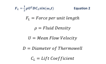
Equation 1 can be used to estimate the force applied to the bottom of the thermowell using about ½ of the distance inserted into the pipe. This choice is justified since the bottom will vibrate more than the location near the pipe wall and will be more sensitive to applied force. Using this force applied perpendicular to the flow as a harmonic force will simulate the actual applied force.
It should be obvious from a review of equations 1 and 2 that for a specific design the exciting frequency is proportion to the flow rate. The force applied is dependent on the Velocity2. So as flow rate increases, the frequency and amplitude both increase.
If the vortex shedding frequency reaches the natural frequency of the system, the thermowell vibration will increase dramatically due to resonance of the thermowell. When this occurs, very high stresses can result in the hardware for the pipe branch that can cause fatigue failures.
One of the common causes of thermowell fatigue failures will be due to flow increases over the original
design criteria for the pipe. This would be common with debottlenecking projects where flow could easily
increase by 20%.
The selection of the thermowell and mounting method would normally be reviewed during the design process to evaluate the vortex shedding frequency as well as the mounted natural frequency for the assembly. It would be reasonable to select hardware with at least a 20% natural frequency separation from the vortex shedding frequency for the maximum design flow expected. If the flow rate is then increased by 20%, it would be possible for the vortex shedding frequency to increase due to higher flow with resonance occurring.
Sample Thermowell
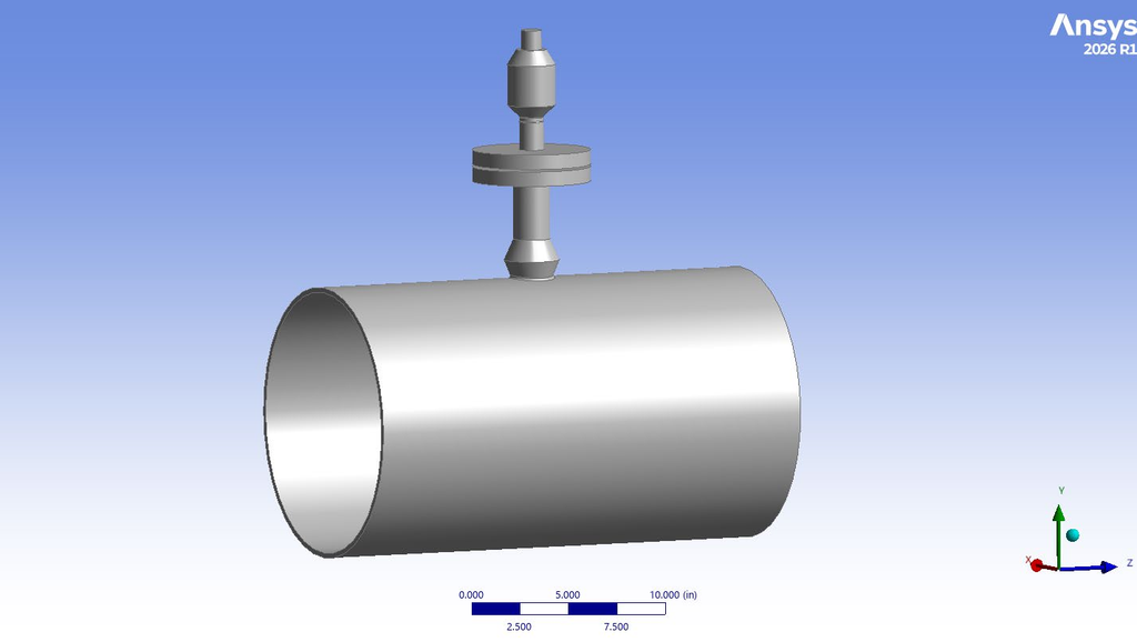
A typical thermowell setup was selected based on provided details for an existing thermowell in a plant. The geometry included a 1 ½” branch line with a flange along with a flanged thermowell that is connected to the main pipe with a WeldOLet. The instrument connection on the thermowell is fitted with a threaded fitting for connection of the temperature sensor. The main purpose for the review was to assess the benefit of using a ZetaQuest Rohr 1.5 would be suitable for installation. In addition, a comparison of the impact of the location of the damper was also to be investigated.
Since the thermowell system will have mounted natural frequencies, the use of a Rohr damper can be effective at adding damping and reducing vibration provided that the mode shape includes vibration near the flange or top of the thermowell since the device is most effective when mounted at a location where the modal vibration is high.
The layout of the thermowell line can be seen below in Figure 1. The model includes thinner pipe to simulate threaded pipe near the fittings connected to the top to better evaluate the impact of positioning the device at several locations. Estimated stress at the threaded fittings were evaluated by calculating the bending stress at the threads (without the threads being modeled) then applying a stress intensification factor (SIF) per ASME B31J.
The main geometry included a WeldOLet at the main pipe with welded pipe nipple to a flange. The flanged thermowell was modeled as provided with it inserted at the flange with dimensions per provided geometry. There was a threaded fitting on the top of the thermowell for attaching the temperature detector (RTD or thermocouple) with a threaded connection to the thermowell.
The options for where to put a Rohr damper included on the end of the threaded component or on the flange of the thermocouple. The location at the end of the threaded fitting was expected to provide better vibration reduction at resonance compared to lower mounting. However, the main purpose for the review is to help assess the impact of stress at the threaded fitting due to the added mass of the damper.
The natural frequencies of the thermowell assembly were calculated so that the frequencies and mode shapes could be reviewed. Two natural frequencies will exist in two directions including the direction of flow through the pipe as well as perpendicular to the flow direction. The two frequencies will include a mode where the insertion portion of the thermowell will vibrate without much motion at the flange plus a mode where the flange and thermowell vibrate together. The mode with the thermowell alone (without the flange and external portion vibrating) is a mode that cannot be easily impacted with an external damper.
The natural frequencies and mode shapes will depend primarily on the length of the inserted component. The lowest natural frequency is the one of concern since it would be likely that the device has the highest risk of failure when the lowest natural frequency is reached by the vortex shedding frequency. The 2nd mode is much less likely to be excited.
Therefore, it is important to confirm if the lowest natural frequency includes large motion at the flange and the external portion of the system so that the damper will be effective.
The two natural frequencies calculated in the perpendicular direction to flow were at 93 Hz and 327 Hz as detailed in figures 5 and 6. The lower mode at 93 Hz has the branch line and thermowell moving together. This mode should be well impacted by the external vibration damper. The 327 Hz mode does not have motion at locations where a damper could be located and would therefore not be a candidate for using a damper to reduce vibration.
The natural frequencies and mode shapes for the modes perpendicular to the pipe flow direction are shown in Figures 5 and 6. Similar modes exist in the pipe flow direction with slightly different frequencies due to the flexibility of the main pipe in both directions. The vortex induced vibration can occur in both directions although the classic consideration is the direction perpendicular to the pipe flow.


Equation 2 was used to calculate the oscillating force at the bottom of the thermowell, with an estimate of 4.16 lbf. This was using Equation 2 for the lower 4” of the device. Using a finite element model, the stress was evaluated using the stated dynamic force and with 1% damping on the system. The maximum stress was identified where the WeldOLet connects to the main pipe as seen in Figure 7. In addition, the stress on the threads of the valve was found to be 2582.4 psi, but a stress concentration factor of 2.3 must be applied to that stress calculated per ASME B31J. Therefore, the actual stress on the threads is 5939.52 psi. In addition, the maximum velocity is 18.64 in/s at the top of the line as shown in Figure 8.
Since the maximum stress was found to exceed a typical limit of 3,870 psi 0-pk at the weld between the WeldOLet and the main pipe, the maximum acceptable vibration would be in the 3.8 in/sec range. That would be the vibration amplitude where the stress at the weld equals the fatigue stress limit stated in API 579 Part 15.


Rohr Damper Application Review
A Rohr 1.5 – 84.2 Hz was found to be the most effective on this branch line in the field with the damper located near the top of the threaded fitting. The dynamic properties for the damper were applied to the end of the valve in the model to observe the stress on the threads and determine if it was a good place to install the damper.
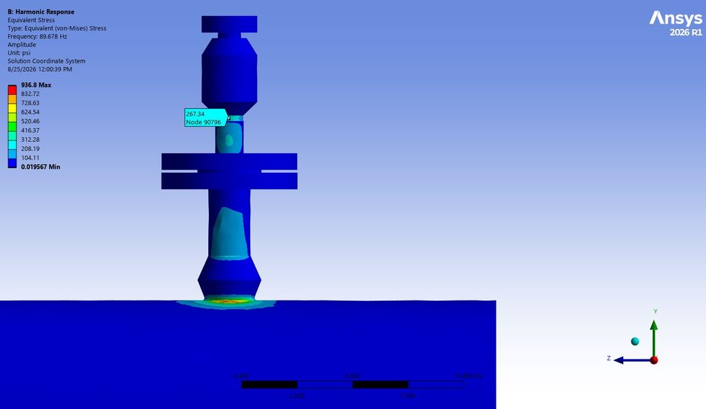
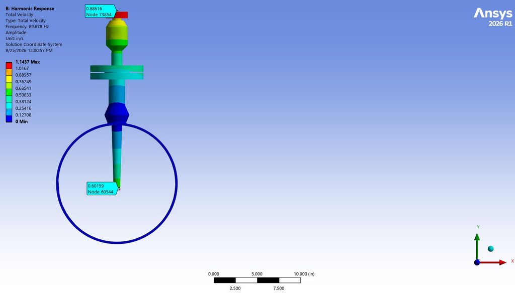
Similarly to the branch line without the damper, the maximum stress would found to be where the WeldOLet connects to the main pipe as seen in Figure 9. The stress on the threads was calculated to be 267.34 psi by the model, so the actual stress on the threads 614.88 psi including the stress intensification factor. Additionally, the maximum vibration was reported to be 0.89 in/s at the top of the branch line when the damper is installed on the end. If the stress in the system was pushed to the limit (3870 psi), the vibration at the end would be 3.66 in/s.
As an alternative to installing the Rohr 1.5-84.8 on the end, the damper was modeled attached to the flange so the added weight of the damper would be located below the threads. To achieve the desired damping levels on the mode that is perpendicular with the main pipe, the Rohr 1.5 – 84.2 Hz had to be swapped for a Rohr 1.5 – 120 Hz.
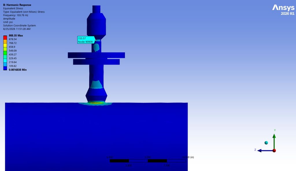
With the damper being installed below the threads, the stress on the threads dropped to 155.57 psi or 357.81 psi with the stress concentration factor applied as seen below in Figure 11. The maximum stress at the weld between the WeldOLet and the main pipe was 988 psi. The maximum vibration at the end of the thermowell line with the damper installed on the flange is 1.01 in/s as seen below in Figure 12. Additionally, the vibration would be 3.94 in/s if the system was pushed to failure and had a maximum stress of 3870 psi. This shows that the flange is the best location in this system to install the Rohr 1.5 for stress reduction, but the vibration is slightly higher than when the Rohr was installed at the end of the branch.

Conclusions
The analysis confirmed that the ZetaQuest Rohr 1.5 is a suitable solution for reducing vibration in the branch line. Installing the damper at the end of the valve decreased stress on the threaded connection, but installation at the flange reduced the stress even more. The vibration when the Rohr was installed at the end of the branch line was the lowest with the flange installation location being slightly higher. Additionally, it is expected that a Rohr 1.5 – 120 Hz will perform better than the Rohr 1.5- 84.2 Hz when mounted on the flange instead of on the end of the threaded hardware. The Rohr 1.5 – 120 Hz installed at the flange is the recommended configuration for this system due to reducing stress and only having a slight increase in vibration compared to the damper being installed at the end of the branch.
| Description | Original design | Rohr 1.5-84.8 at top | Rohr 1.5-120 at flange |
| Maximum vibration | 18.6 in/sec pk | 0.89 in/sec pk | 1.0 in/sec pk |
| Maximum stress at WeldOLet | 19,122 psi pk | 937 psi pk | 988 psi pk |
| Stress at threads | 5,939 psi pk | 614 psi pk | 359 psi pk |
| Maximum vibration limit | 3.77 in/sec pk | 3.68 in/sec pk | 3.92 in/sec pk |
Works Cited
1. Blevins, R. D. (2001). Flow-Induced Vibration (2nd ed.). Krieger Publishing Company.