
Reciprocating Compressor Piping
Description
Reciprocating pumps and compressors are known to produce moderate dynamic forces due to the pulsation generated by the reciprocating pistons. The typical design guideline for the piping is to have adequate supports and short enough spans between supports to produce piping mechanical natural frequencies that are 20% higher than the highest significant pulsation order.
For reciprocating compressors the significant orders will include 1x, 2x, and other harmonics depending on the cylinder arrangement. Reciprocating pumps will commonly have a maximum significant order of either the number of cylinders or twice the number of cylinders.
While the guidelines are clear in API standards for the piping associated with the compressor, guidance is not specifically detailed for piping on other equipment that may share common pipe supports or structure. In this case, a centrifugal pump was installed so that the discharge pipe on the pump shared a common support with the reciprocating compressor.
During plant commissioning, extreme vibration was identified on the centrifugal pump discharge piping when the reciprocating compressor was operating. Field testing confirmed that the pipe was vibration at 1xRPM of the compressor due to transmitted vibration at the common pipe support.
Analysis
Vibration was measured on the common support and found to be extreme (>2 in/sec pk). The support was modified by stiffening the design to increase the lowest natural frequency at the support to 20% above 6xRPM on the compressor. This modification was successful at controlling the compressor piping, but the pump discharge pipe was still excessive.
The pipe was tested for natural frequencies using a simple bump test and a vibration data collector. Measured natural frequencies were identified at 7.81 Hz and 14.38 Hz, with the higher frequency only 3.7% away from 2xRPM on the compressor.
Even the relatively small amplitude of vibration remaining at 2xRPM was found to produce HUGE vibration on the pump piping. The field testing not only confirmed the natural frequency but also the as built damping level. The bump test confirmed that the original damping was about 0.9% of critical damping. With that low of a damping level, vibration at the compressor support would be increased by a factor of up to 53.6 on the pump piping due to the resonance.
Since a comfortable operating vibration amplitude on the pump piping would be < 0.5 in/sec pk, that would require pipe support vibration of less than 0.009 in/sec pk at 2xRPM.
The pump discharge pipe layout was used to calculate the pipe natural frequencies and mode shapes to understand how the pipe was responding to the compressor vibration. Bentley Autopipe software was used to calculate the natural frequencies and mode shapes with the two natural frequencies shown in figures 1 and 2.
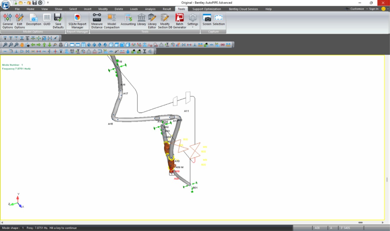
Figure 1 - First Natural Frequency at 7.8 Hz

Figure 2 - Second Natural Frequency at 14.4 Hz (3.7% separation)
Modification
A field review identified that there was a rather stiff column located near the vertical run on the pump discharge pipe that could be used for restraint. A single Model B ZetaQuest damper was installed at about a 45 degree angle to the model axes to have significant effect on both natural frequencies.
Results
After the damper was installed, the pipe was impact tested to evaluate natural frequencies with the elevated damping. The X and Z directions (where vibration was elevated) were confirmed to have natural frequencies essentially eliminated to well above 2xRPM on the compressor. The test results are shown in figures 3 and 4.
Operation with the damper in place eliminated any vibration concerns for the centrifugal pump. As confirmed by test, the discharge pipe natural frequencies were functionally eliminated up to 100 Hz.
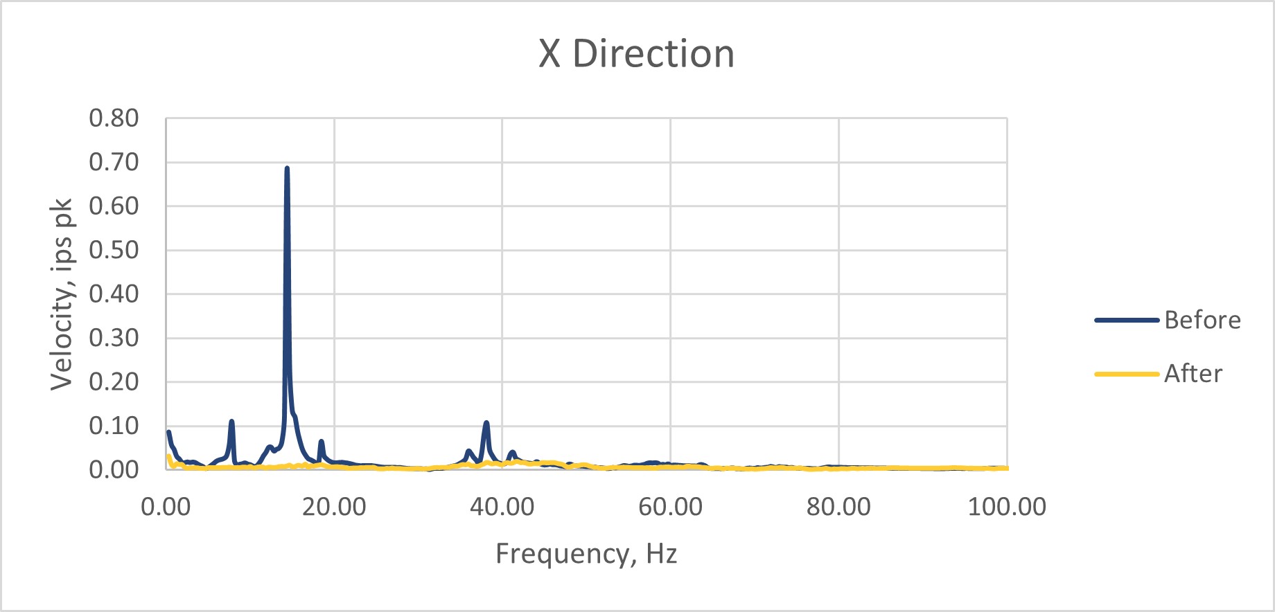
Figure 3 - X Direction Results
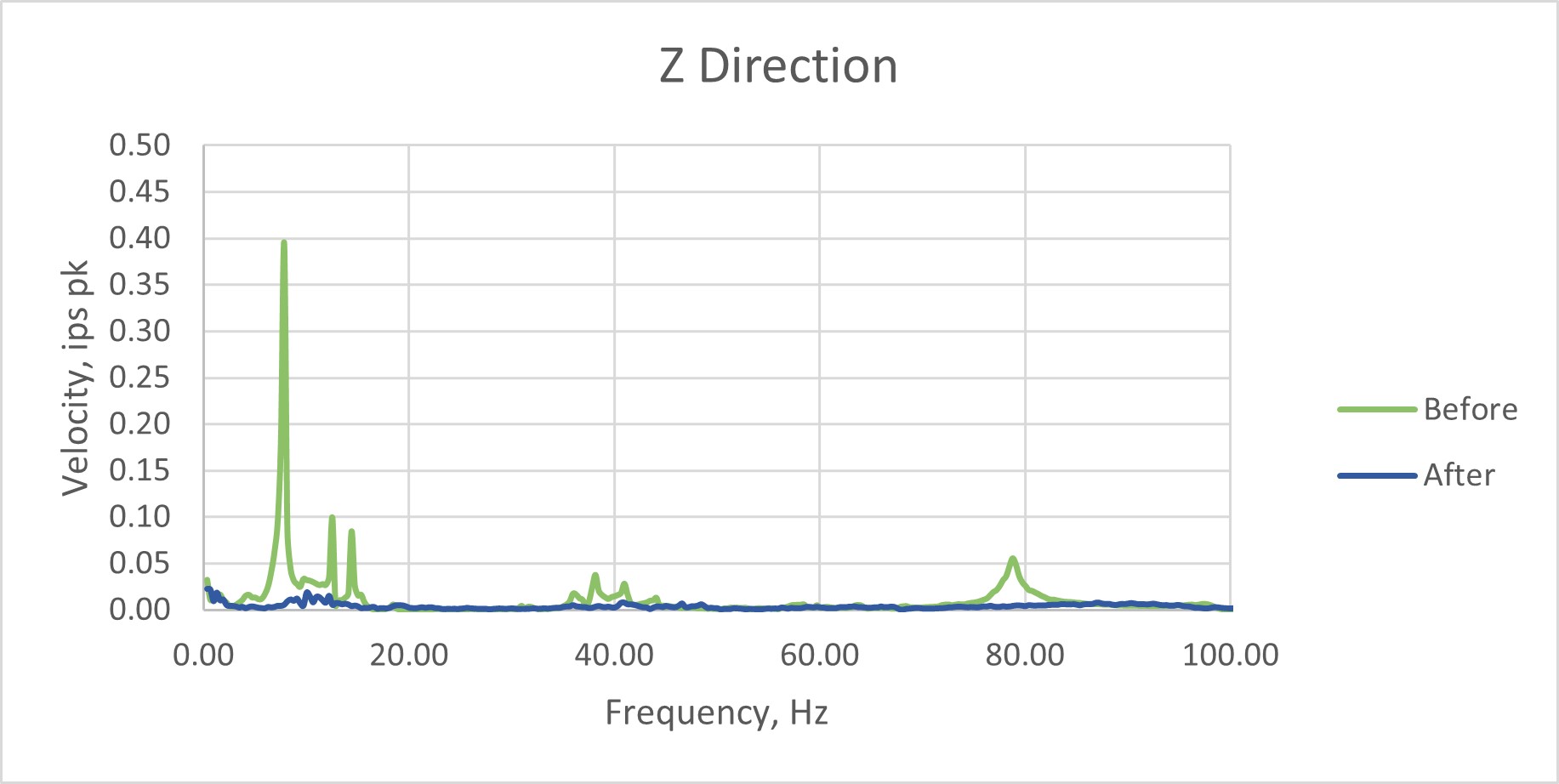
Figure 4 - Y Direction Results