Static Mixer Vibration
Description
A static mixer is a piping component that is used to mix two liquid streams for applications such as acid neutralizing or other chemical mixing services. The device functions by having high turbulence to cause or promote efficient mixing of the two fluids that is often accomplished using high local velocity and/or a variety of blades or other tortuous paths to improve the mixing efficiency.
Since the mixing of the two fluids will tend to be somewhat violent by intent, it is normal to have moderate vibration particularly if the mixing tends to produce gas along with liquid. As a result, the piping will either have moderate to high levels of random vibration forces near the mixer or will have slug flow reaction forces downstream of the mixer. Either way, the mixer and the associated piping will vibrate with dominant vibration at mechanical natural frequencies.
The actual vibration amplitudes will depend on the physics of the mixing, the stiffness of the pipe supports near the mixer as well as vibration damping in the piping network. It is not uncommon for mixing reactions to be exothermic so that the pipe operates moderately hot so that thermal growth concerns prevent using a number of stiff piping supports.
Alternatively, vibration dampers that are appropriately sized and located can greatly reduce or eliminate resonant vibration while having no impact on static stress so that large thermal growth can be tolerated while still supporting the piping dynamically.

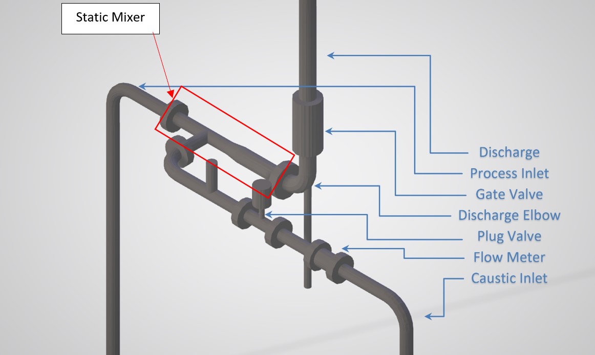
Figure 1 - General Layout
Field Assessment
A static mixer was installed to neutralize an acid stream using caustic. The static mixer included a process inlet line and a caustic line upstream of the static mixer with a single outlet pipe that flowed upward to a tank.
An initial assessment showed that the piping near the mixer had large vibration with amplitude of 2 in/sec pk with frequent vibration in the 0.2 inch pk-pk range. Vibration was dependent on flow rate through the mixer, with higher total flow producing higher vibration.
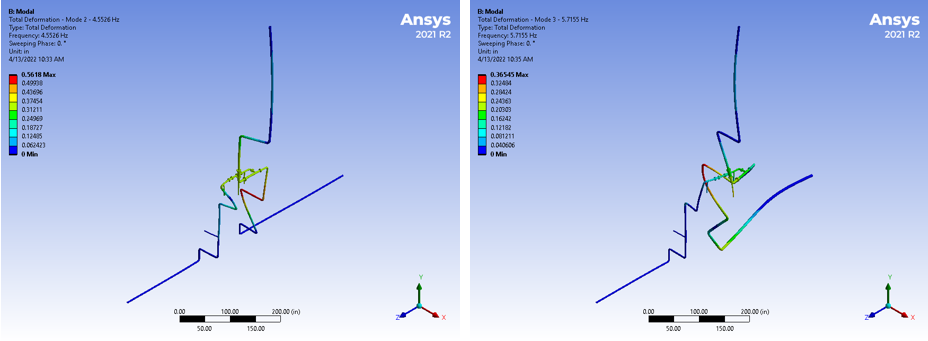
The response was dominant at two different frequencies, with one in the north/south direction at about 4 Hz as shown in figure 2 and in the east/west direction near 6 Hz as shown in figure 3.

Figure 2. First mode shape (4 Hz), showing primarily East/West direction motion
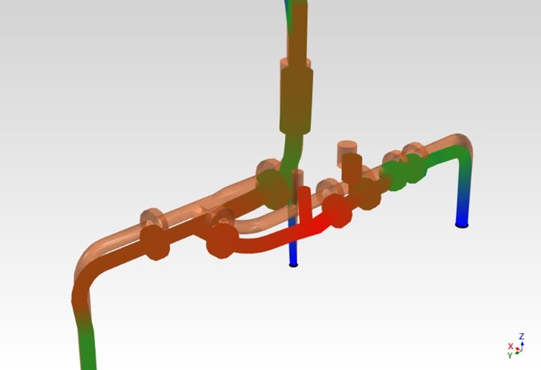
Figure 3. Second mode shape (6 Hz), showing primarily North/South direction motion
Analysis
The pipe network was modeled using ANSYS finite element modeling software to identify/confirm the natural frequencies and mode shapes for the piping associated with the mixer. Two natural frequencies were identified in the finite element analysis as shown in figure below with modal response similar to that observed in the field. The frequencies and mode shapes are shown in figure 4.

Figure 4 – Calculated Mode Shapes and Natural frequencies
Modification
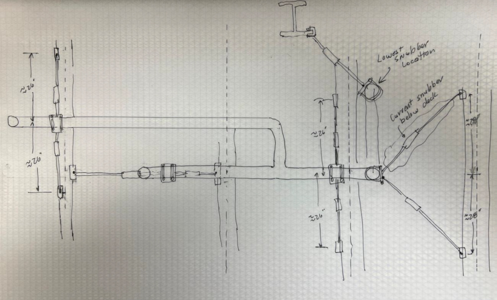
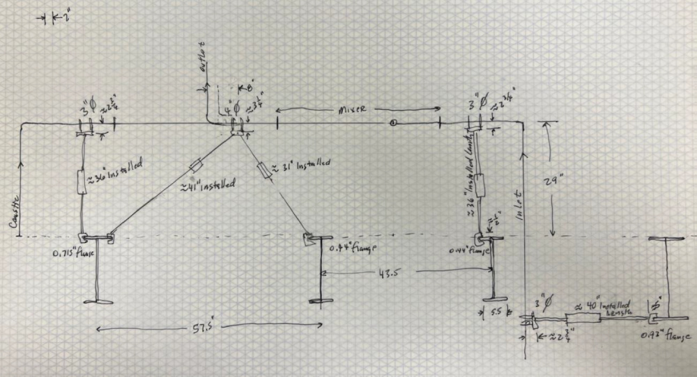
Since the mixer was located on a steel deck with reasonably sized I-beam supports, vibration dampers were investigated to help control vibration of the piping with the dampers installed from the mixer piping to the steel deck below. After reviewing possible locations and benefits observed from the added damping, the following modifications were selected.


The design included adding 9 individual dampers oriented in both north/south and east/west directions as well as on the inlet pipes further away from the mixer. The calculated natural frequencies and damping ratios after adding the dampers were as follows:
| Description | Frequency, Hz | Dominant Direction | Damping Ratio |
|---|---|---|---|
| Mixer and Feed Pipe | 6.1 | North/Sount | 38% |
| Mixer (Targeted Mode) | 6.7 | East/West | 59% |
| Mixer and Feed Pipe | 7.3 | North/South | 18% |
| Inlet Pipe | 12.4 | Mixed | 20% |
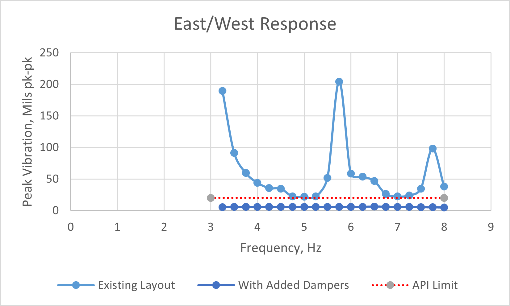
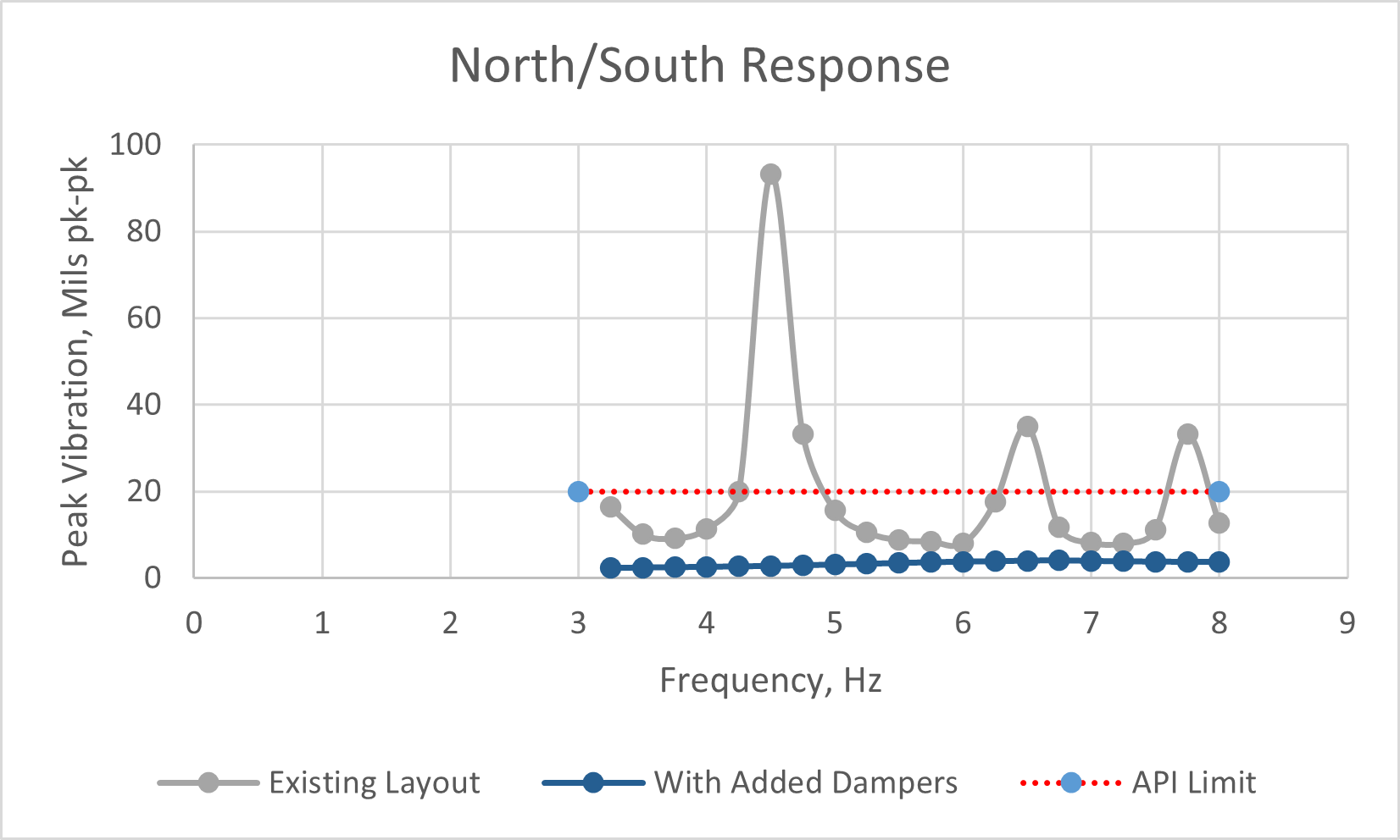
The damping ratios are relatively high, with any mode with a damping ratio above 20% by definition in API 684 being a non-resonant frequency due to the lack of response. The high level of damping is confirmed in figures 5 and 6 by the nearly flat response through the 3-8 Hz range modeled. So the final solution essentially eliminates natural frequencies in the vicinity of the mixer so that vibration should be minimal.
Modified Results
After the dampers were added, the vibration response as predicted in figures 5 and 6 was realized with acceptable operation at high plant rates. A bump test was done to confirm the natural frequencies and damping levels in the frequency range up to 10 Hz which was the design target. As detailed in figure 7, there was no responsive natural frequency observed below 10 Hz.

Figure 5 - East/West Response

Figure 6 - North/South Response

Figure 7 - Impact/Bump Test Result on Mixer after Added Dampers
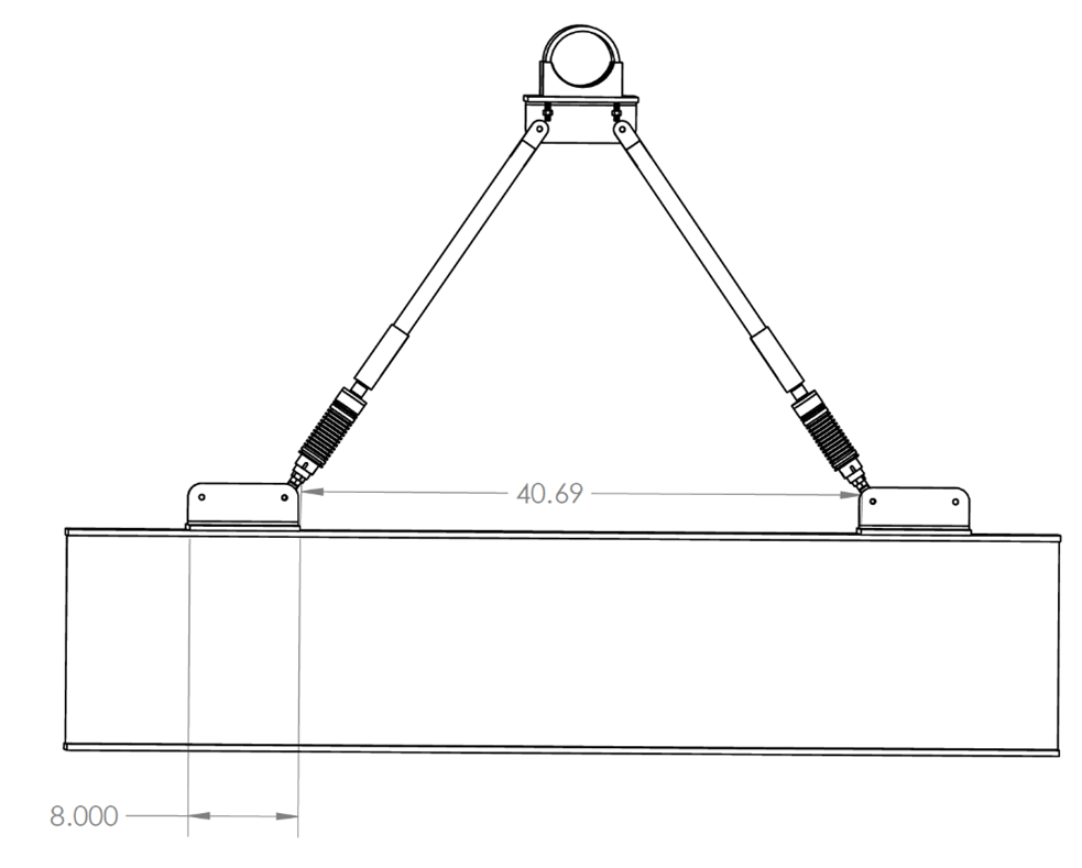
Figure 8 - Typical Installation