
Starr Dampers Stop Two Phase Flow Piping Vibration
Description
A two phase flow line was found to produce excessive vibration on a large (24” and 30”) pipe run with vibration as high as ½ inch pk-pk in two directions. The vibration was observed to be highest near an elbow located downstream of a control valve.
Any time there is a two-phase line service (mixture of gas and liquid) it will be common for there to be occasional (or steady) pulsing on the line when slugs of gas and liquid pass elbows (turn in direction of flow). When this occurs, the pipe can shake violently at the lowest natural frequencies.
Field Assessment

The pipe was reviewed in the field with visual observation of large motion primarily at the elbow following the vertical run downstream of a control valve.
The vibration included side to side vibration near the elbow along with large vibration in the direction of the long horizontal run. Since the vertical run before the elbow had a 45 degree turn there, any slugging flow would tend to produce shaking forces both side to side and along the long horizontal run.
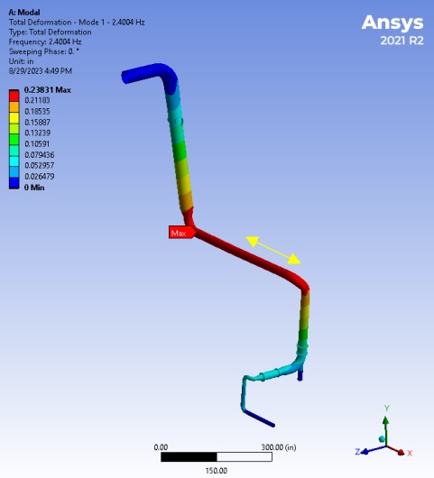
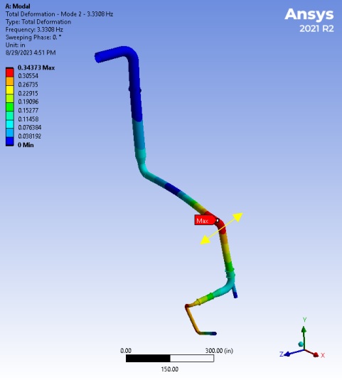
The vibration was visually observed to be at two distinct frequencies including one right above 2 Hz and another above 3 Hz.
Analysis
The pipe network was modeled using ANSYS finite element modeling software to identify/confirm the natural frequencies and mode shapes for the piping run.
The lowest two natural frequencies were calculated to be 2.4 Hz and 3.3 Hz with mode shapes that were identical to the field observations. A dynamic force was applied to the model to estimate the amount of force required to generate the observed vibration to assist with reviewing modifications based on an estimate of 2% model damping on the existing piping system.
The equivalent harmonic force required to excite the 2.4 Hz mode to produce ½” peak to peak vibration at the elbow was only 19.75 lb along the horizontal run. The 3.3 Hz mode excitation only required 20.66 lb perpendicular to the long horizontal run for the same ½” pk-pk vibration. Actual peak forces from slug flow would be larger, but identifying an equivalent force as described provides a useful basis for assessing modifications by adding vibration dampers or other pipe system modifications.
Modifications
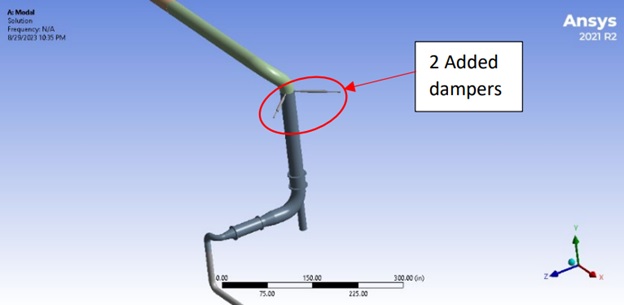
Review of the site identified that there were rather rigid columns near the elbow where the highest vibration was observed that could be used for tie points for vibration dampers. The ANSYS model was then used to evaluate the benefit of available options including damping hardware.
The pipe did operate at moderate temperature, so it was necessary to accommodate about ½” of thermal movement near the possible tie point relative to the structural steel columns. This requirement limits the options for vibration control options since adding a normal support would greatly increase the static stress due to the required thermal flexibility.
ZetaQuest Starr dampers are designed with no static stiffness, with the size dampers selected to have +/- 1” of static travel range. Therefore, the added devices will have no impact on static stress on the pipe run while resisting dynamic motion.
An arrangement of 2 Model D dampers was selected and oriented as shown below. There were two dampers mounted about 90 degrees apart in the horizontal plane and attached to rigid structure adjacent to the line near the elbow as shown.
Modified Results
After the dampers were added, the 1st natural frequency was found to increase to 3.35 Hz with a damping ratio of 34.4%. The second mode increased in frequency to 5.28 Hz with a damping ratio of 55%. Based on several accepted standards, these frequencies are no longer resonant due to the high damping levels present.
Although the dampers have no static stiffness, the large damping and general dynamic response will push natural frequencies higher as described while still producing heavily damped modes. API 610 Annex I, paragraph I.1.3 describes required separation margins and states that damping higher than 15% or critical damping or amplification factor < 3.33 is considered to be critically damped due to lack of response. Since the damping levels in this case exceeded this threshold, the line is now considered critically damped.
Using the same forces as used above for the original model, the final vibration was calculated to be 0.007” pk-pk for the 1st mode and 0.004” pk-pk for the 2nd mode. As a general guideline for assessing vibration below 20 Hz, API 618 figure 618-4 and paragraph 618-7.9.4.2.5.2.4 state that design vibration for piping below 20 Hz is 20 mils (0.020”) pk-pk at discrete frequencies below 20 Hz.
Field Experience
After installation of the two dampers as described the
vibration on the line was eliminated to within calculated ranges. No further
issues were present, and the plant could now operated up to full rates due to
acceptable vibration through the entire operating flow range on the line.