Starr Damper

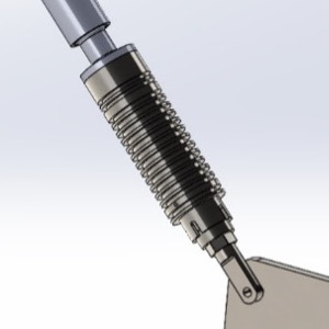
The ZetaQuest Starr Damper functions as a dashpot as commonly described in mechanical systems. The dashpot is the damping source for the system with the damping given by the character C.
Most commonly identified with mechanical system, the damping level is described as a percentage of critical damping using the symbol ζ (Zeta), where a level of ζ = 50% critical damping will produce no amplification at the resonant frequency and result in the resonance not being observed.
When ZetaQuest Starr dampers can be added to a mechanical system, the vibration when operating near the resonance can be dramatically reduced.
Starr Damper Installation
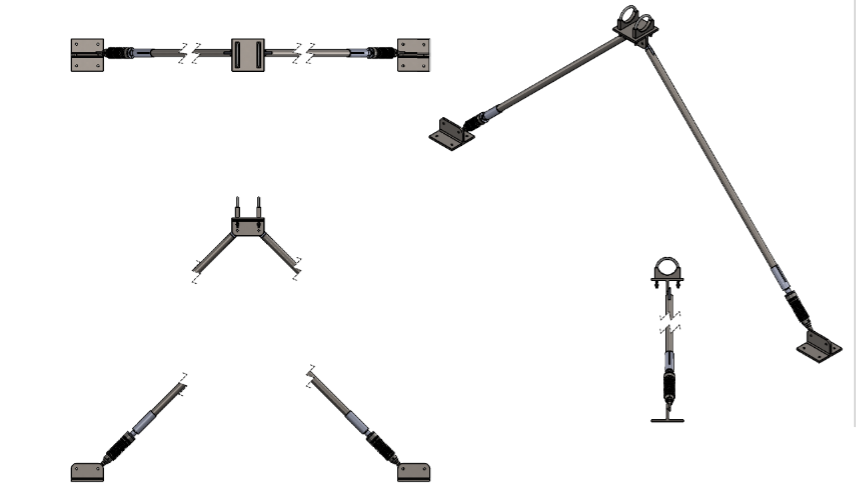
Most commonly they are installed in pairs with dampers arranged to resist the vibration in a plane. Common arrangements are shown to the left.
The connection to the pipe is done with a custom pipe clamp. Clamps are normally lined with gasket material to reduce the risk of wear between the clamp and the pipe. The damper is positioned between the pipe and the tie point with the extension tube length adjusted during assembly.
Termination plates allow for anchoring to a floor, heavy beam, etc. by bolting or the plates can be welded in place.

Starr Damper Sizes
| Model | Travel Range | Damping level, Lb-sec/in | Approximate Pipe Size* |
|---|---|---|---|
| A | +/- ½” | 30 | ½” - 2” |
| B | +/- ½” | 70 | 2” - 3” |
| C | +/- ¾” | 166 | 3” – 6” |
| D | +/- 1” | 390 | >6” |
Note: * Actual selection of devices depends on the mass of the moving pipe or structure and the resonant frequency. Contact us to discuss your application.
Starr Damper Applications
Starr Damper Documentation
- Brochure
- Manual